


How to take apart your PSP
In this lesson you are going to find out how take apart your PSP. Please Note: This will make your PSP warranty void!
1. The Gear
Before attempting to take apart any electronic device, make sure you have
the right gear and location. You don't want to lose screws or other parts
to kids, dogs, or a sudden blast of air. For the PSP you really only need
one small flat head screwdriver that you can use for prying, and a Philips
head screwdriver to remove the screws. A pen/paper might also be useful
for remembering where the screws go. If you are a professional, then you
might want to ground yourself using a static strap to prevent any sudden
static discharges from killing your PSP.
2. Removing
the cover
The first step to taking apart any device is to locate the screws keeping
the outer shell on the device. In the case of the PSP, you will have to
remove three screws. The first two are easy to find and are on the back
right side of the PSP near the Duo stick slot (black). The third screw
is on the bottom side of the PSP right in the center of the system. The
final two screws are actually hidden away in the battery cavity.
You will be able to see one black screw and one silver screw once the battery is removed. You can remove both of them, but it is the black screw that is responsible for keeping the case together. The silver screw is there to keep the LCD holder in place.
The final screw is actually under the PSP Void warranty sticker that is at the lower side of the battery cavity. Don't touch that warranty sticker unless you are sure you want to go inside. It is not easy to get one of these off without causing the sticker to show evidence of tampering. With the sticker removed, you will once again see a black and silver screw. Remove the black one at this time, and keep in mind the silver screw for later. Once the black screw is removed, you should be able to lift the top of the PSP case off the device and view the internals (see Figure 1 for illustration).
3. Removing
the LCD
With the cover off, the next step appeared to be to remove the LCD display.
After poking around for a few seconds, I noticed the there was a button
bar across the bottom of the LCD that would have to be removed. This pops
off easily by lifting the silver catch on the left side of the display.
You can then carefully remove the bar by lifting the tan catch on the
connector and pulling out the circuit strip.
See figure
1 below - PSP with top cover removed
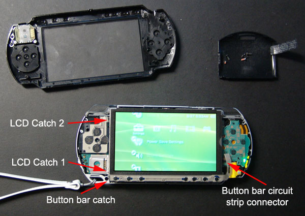
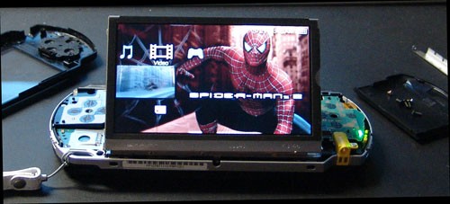
Removing the screen is a bit more challenging. I wasn't sure at first where to start, but eventually trusted my gut instinct and went with the brute force method. My target was the left lower corner of the LCD tray. You insert a very narrow screwdriver in between the screen and the metal piece holding the analog joystick board (LCD Catch 1 in Figure 1). Then pry the screen up slowly and the metal wedge should pop out of the catch in the lower left part of the display tray. Next do the same on the top left side of the display (LCD Catch 2 in Figure 1). This should allow you to wiggle the screen up and out. Just be careful not to pull to fast or hard because the display is connected to a circuit board underneath with two circuit strips (Figure 1). Now that the screen is released from its holder, I wonder if my screen can become adjustable, as illustrated in Figure 2.
See figure 2 below - Angled LCD screen
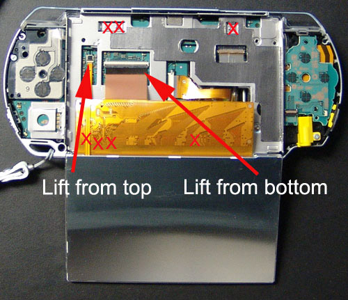
With the LCD out of the tray, we need to remove it from the PSP. This is accomplished by removing the circuit strips from the main board of the PSP. To do this, first lift the black part of the connector on each strip. The long connector lifts from the bottom, and the short connector lifts from the top (Figure 3 for details). Before removing these connectors, make sure you take out the battery. You don't want any current flowing through the PSP causing you problems!
See figure 3 below - Removing the LCD screen
Next, you need to remove the metal tray that held the LCD, which is tricky because it is linked to the UMD release on the top of the PSP. So, carefully make sure that you have removed all visible screws that hold the tray down (note where each screw is to be placed when you rebuild the PSP, and also make sure you remove the two screws from the battery cavity (these might have been removed by you earlier). These will be silver screws, not the previously removed black screws. Once all the screws are removed, open the UMD door and then lift the display tray off the PSP. Figure 3 shows you the general location of the screws.
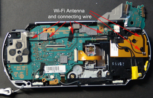
4. The Wi-Fi
Antenna
Earlier I had noticed what I thought was an antenna on the right side
of the PSP under the PlayStation controller circuit board. To verify this,
I slowly pried the circuit board over the upper catch and lifted it up
off the PSP. This piece could be fully removed if you wanted to take out
the Right trigger button, but I just wanted it out of the way. To achieve
this, I simply lifted the circuit strip connector and flipped the controller
circuit board over the top of the PSP. This gave me a clear shot of the
antenna and its connecting wire, as detailed below (Figure
4). With this now laid bare, it would be fairly easy to add my own
external antenna. However, if the WNIC had a connector on it that I could
plug into, the embedded antenna could be complete stripped!
See figure 4 below - WiFi antenna and connecting wire
The Main
Circuit Board
Next I targeted the main circuit board from the PSP. This proved to be
difficult. First I had to remove one screw previously hidden by the LCD
tray. Then I had to remove the left side PSP controller, which was snuggly
inserted between the circuit board and the case of the PSP. Removing this
once again involved lifting a circuit strip connector, but by now you
should be familiar with how this process works. Next I had to disconnect
a circuit strip located near the bottom of the PSP that connects the UMD
drive to the main board. Once this piece was disconnected, I slowly worked
the circuit board up off the PSP. As I learned, the board was connected
to the rest of the PSP via a male/female connector. This connector is
located almost directly under the LCD connectors on the circuit board.
As a result, you can leverage the circuit board up by using the upper
left of the PSP to push the board out of the male/female plug. Figure
5 shows you what the PSP should look like at this point. You can optionally
remove the small connectors at the bottom of the PSP that connect up to
the speakers. However, for my purposes, I left these connected and simply
flipped the main board over once it was removed.
See figure 5 below - PSP without circuit board
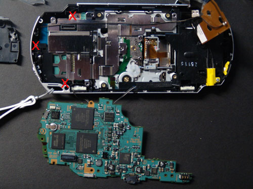
5. Getting to the
Wi-Fi Card
I was still not at the Wi-Fi card! Beneath the main circuit board is a
grounding/protector plate. This is easy to remove, and only requires the
removal of three more screws, as indicated with red X's in Figure
5. Once these screws are out, you first have to take out the plastic
black piece, which then allows the silver shield to be removed. I could
finally see the Wi-fi card, which simply lifted out the PSP. As I had
hoped, the antenna was indeed connected to the card via a socket connector.
In addition, I also noted that my WNICs hardware address was stamped onto
the cards surface. Finally, I also should note that the Duo stick slot
is also integrated into the same circuit board as the WNIC.
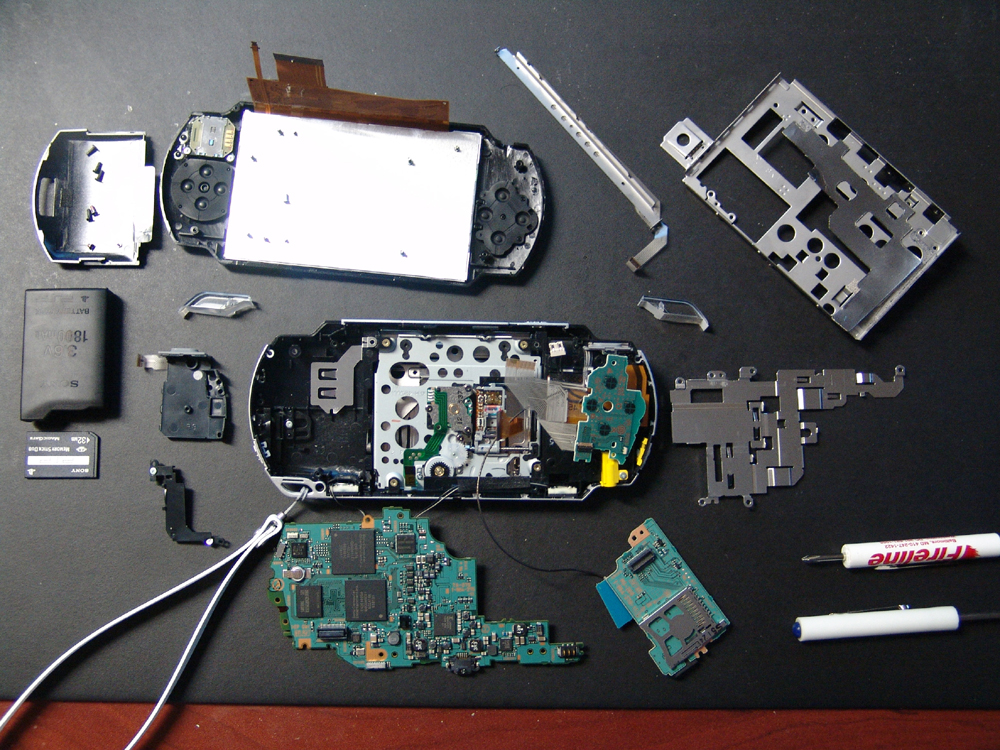
Figure 6 below shows the PSP complete disassembled in all its glory!
Please note: We take no responsibility for you breaking your PSP whilst following these instructions.
Full credit for these instructions goes to Seth Fogie of www.informit.com!